Pipe flange design for high temperatures (+ 600℃)
- ASME Flanges
- Design requirements for high temperature flanges
- Edge Supported Lap Joint Flange with Rotational Adjustment
- Edge Supported Lap Joint Flange with Rotational and Angular Adjustment
- Design Justification
1. ASME Flanges
a) High bolts loads and high flange stresses
Traditional ASME B16.5 flanges use inside bolt circle sheet gaskets, spiral wound gaskets or solid metal rings. High bolt loads are required to achieve the necessary gasket or sealing ring seating stress to achieve a leak free joint.
The bolt tension required to seal an ASME flange with a spiral wound or non-asbestos sheet gasket is often very much higher than that required to withstand pressure and external loads. i.e. The primary design requirement for both flange design and bolt size is to create a seal.
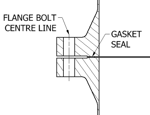
The design of ASME flanges create a large eccentricity between the point of action of the bolts and the clamping force applied to the gaskets. (See Fig 1). The eccentricity between bolts and gasket clamping force causes the flange to deflect. (See Fig 2).

b) Material strength at high temperatures
The maximum temperature of an ASME flange is limited by material properties. The strength and stiffness of the bolts, flanges and gaskets reduce as the temperature increases.
Material stiffness reduces as temperature decreases reducing gaskets sealing stress imposed during installation. For example, the elastic modulus of most austenitic stainless steel reduce by 25% at temperatures of 650℃.
c) Materials are subject to creep as the temperature increases.
Material strength and stiffness might be sufficient to achieve a tight joint. However, creep will cause the flanges and bolts to relax over time. If creep strain rates are high enough and the plant operating life long enough, then the gasket seating stress will eventually reduce and the flanges will leak.
For example, two options might be used for 316 type stainless steel flanges welded to 316L pipe.
Option 1. Using a stabilised material. e.g. 316Ti. (Relatively high cost and long delivery).
Option 2. Weld 316L stub pipes “pup pieces” to rough machined 316 flanges. Heat treat the welded assembly and finish machine. (Relatively high cost and long delivery).
The complete flange assembly is significantly longer than standard flanges. The pipe layout would be less compact.
d) Gasket Materials
Gasket material for use at high temperatures tends to be relatively hard. Options for “soft” gasket filler materials are even more temperature limited than for the metal bolts and flanges. As temperature increases, organic gaskets filler need to be replaced by inorganic materials. e.g. Mica. Inorganic materials are even harder. Even higher bolt loads and flange stiffness are required to achieve and maintain flange sealing stress..
e) Material costs
Metallic materials for flanges and bolts for temperatures approaching and exceeding 600℃ need to be high alloy to maximise both strength and creep strength. High alloy materials are normally very expensive. For example, high alloy bolts for DN300 ASME flanges could cost several hundred pounds – each! The cost of high temperature spiral wound gaskets could also be similarly expensive. Gasket costs increase even further if there are purity requirements for the filler materials or a need to test the gasket at design temperature.
2. Design requirements for high temperature flanges
A high temperature pipe joint should include the following features
a) Low sealing forces to allow
i) The smallest and cheapest bolts with minimum strength with least favourable creep properties.
ii) The thinnest possible flanges subject to the lowest installed stresses. Low installed stresses will also permit the use of the cheapest materials with least favourable creep properties.
iii) The use of un-welded high stress parts to avoid welding problems with mixed material welds and post weld heat treatment.
b) A displacement controlled gaskets – seals rather than stress controlled seals.
i.e. Sealing performance based only on ensuring the joint remains closed rather than on maintaining a minimum sealing stress.
c) A fully metal seal when product contamination is a factor.
i.e. To avoid the need to source and test the purity of non-metallic gasket filler materials.
d) A proven seal design for the pressure and temperature.
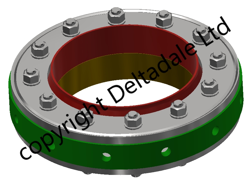
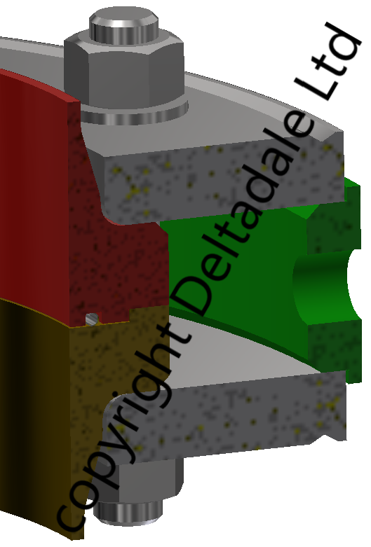
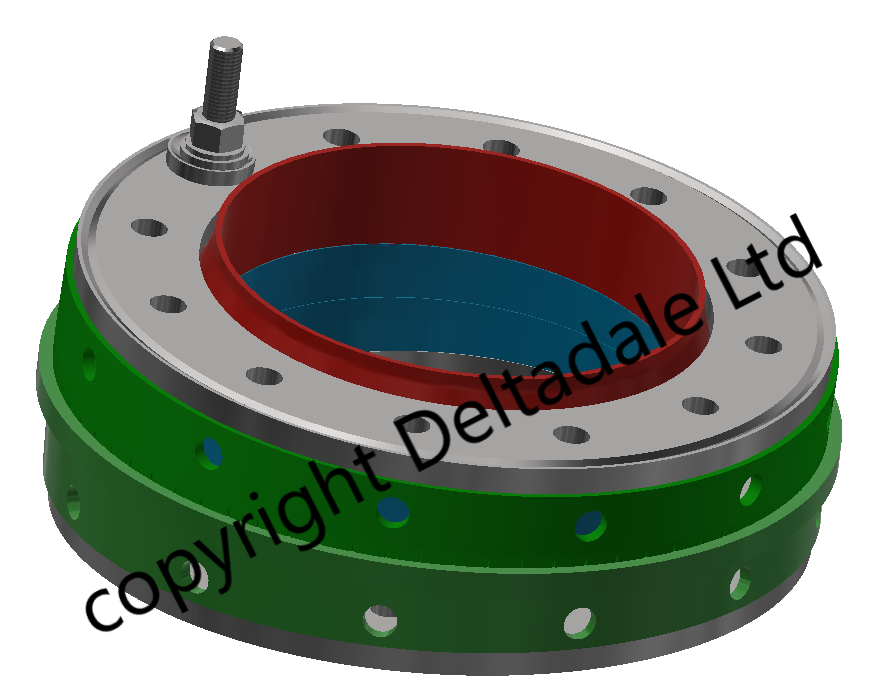
3. Edge Supported Lap Joint Flange – Features
The ESLJ flange (Fig 3) has the following features
a) Flanges
The flanges are lap joint type. Lap joint flanges have two benefits.
i) Infinitely rotational adjustment around the pipe axis.
ii) Welding is not required. i.e. Material choice is not be dependent on the need for welding and / or post weld heat treatment.
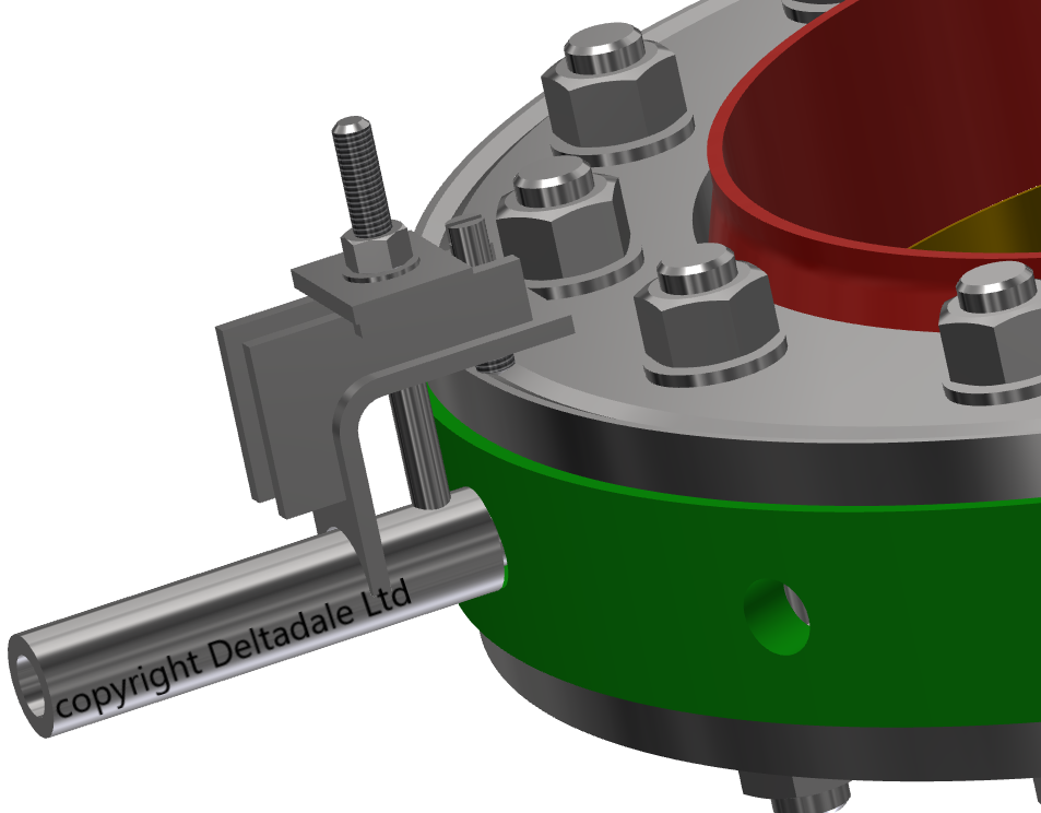
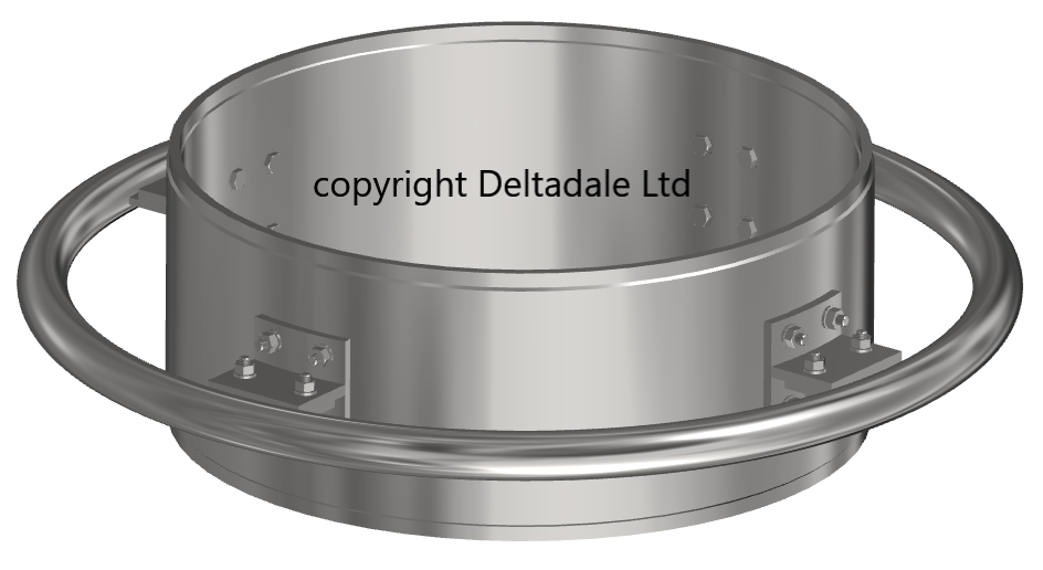
A groove in the flange provides engagement for the installation alignment clamp (See Fig 5). i.e. The edge support ring would be clamped to one of the flanges to assist installation.
b) Edge support ring
The edge support ring prevents the flange twisting and minimises bending. (See Fig 6). It is noted that the edge support ring reduces the available bolt load to clamp the joint. However, the proportion of bolt load required to compress the seal ring is negligible when compared with a traditional spiral wound gasket or solid metal ring type joint (RTJ). The residual bolt load is more than enough to resist pressure and external loads.
Stress levels in the flanges are very much lower than for a comparable ASME flange. Stress levels are also low when compared with the the 1% creep life for 316 stainless steel at say 600℃.
Openings in the edge support ring are proved for installation tools (See Fig 5), inspection of alignment and for leakage (sniffer) testing.
c) Open and hollow section metal seals
i) Profile
The flange is sealed with a thin walled hollow or open section profiled ring. (See Fig 4). The ring cross section could have an “E” or “C” or “O” profile. “E” profile seal rings for lower pressure applications have an extremely low clamping stiffness. “C” profile seal rings for medium pressure require a higher clamping force – but still small when compared with a spiral wound gasket. Hollow “O” rings for high pressure applications require the highest clamping force.
ii) Materials
Seal ring materials for high temperature must be creep resistant to prevent loss of joint sealing stress. The relatively small size and thickness of the seal rings enable economical use of the best possible high cost materials. Seal materials include Nickel Alloy X-750 and Nickel Alloy 718.
iii) Plating
Metal seal rings can be metal plated to ensure very low leakage rates in critical applications.
Plating materials include silver (430℃ Oxidising, 650℃ Non-oxidising), Gold (930℃), Copper (930℃), Nickel (1200℃), Lead (200℃), PTFE (230℃). (Maximum temperatures refer to the plate maximum operating temperature. The chosen seal ring material could be more limiting).
iv) Seal costs
Metal seals are not as frequently used as conventional gaskets for ASME flanges. Shorter production runs might affect prices. Unit costs are likely to be higher than for ASME flange gasket – BUT NOT always. A gasket alternative might be significantly more expensive if it requires bespoke design. Functional testing and material purity testing are both expensive and time consuming.
The cost of metal seals should be considered as part of the total cost of the joint. Even if the seal cost is higher, the joint will be lighter and the bolts cheaper. The number of bolts will be fewer and smaller. For example, ESLJ flange bolting for operating temperatures over 600℃ could be significantly cheaper than bolts for an ASME type flange.
The lower clamping forces and “E” or “C” ring might mean that lesser grade bolts might also be practicable option. Lesser grade is a relative term at very high temperatures. However, the lower clamping forces might allow “only” A286 / Alloy 660 (1.4980) bolts rather than Inconel Alloy 718!
Tip! Always consider the cost AND delivery of bolt replacement during plant operation when selecting high temperature flange joints. Operational costs could be very much higher than expected if high alloy bolts need to be replaced – if you can get them when you need them! Lower bolts stresses at higher temperature will mean less creep strain in a given time. Less creep strain means less risk that the bolts will need to be replaced as frequently.
v) Seal ring suppliers
UK
Sealco International Ltd. (Contacts Application, Information) (Product details sealco_metal.pdf).
Europe
HTMS NV – High Tech Metal Seals (Contacts Applications, Information)
d) Pipe ends
The joint ends should be stress relieved after rough machining to ensure that warping does not occur during operation at high temperature.
The sealing surfaces require a higher tolerance of surface flatness and roughness than a typical gasket. The sealing surfaces are “set-back” in the pipe ends to reduce the risk of damage. (See Fig 4)
The seal rings are displacement controlled by the dimensions of the seal faces. The purpose of the flange bolts is only to maintain metal-to-metal contact of the joint. A loss of bolt tension due to creep would not be a factor provided that the remaining bolt tension was enough to prevent joint separation.
4. Edge Supported Lap Joint Flange with Rotational and Angular Adjustment (Fig 6)
a) Method of angular adjustment
A continuously variable angular adjustment of up to 5 degrees in any direction is achieved by the use of wedge seal-ring carriers.
The joint is fitted with two wedge seal-ring carriers and a total of 3 metal seals. Rotation of the wedge seal-ring carriers relative to each other allows adjustment in any direction. An animation of the angular adjustment is shown in Fig 7.
Note! Angular and rotational adjustment is static and can only take place during installation before bolt tightening.
b) Bolting
Flange bolts are fitted with spherical cup and matching spherical washers to follow the angular adjustment of the flange faces.
c) Edge support
The edge support-ring is replaced with a pair of wedge support-ring which correspond to the wedge seal-ring seal carriers.
d) Graduations
The wedge seal-ring carriers and the wedge support rings are marked with graduations. The graduations allow the angle of adjustment to be set by rotating the wedge rings relative to each other and relative to the pipe.
e) Installation
Installation would consist of first locating and measuring the narrowest and widest points between mating flanges. A line through the widest and narrowest points would become the “joint axis”. The wedge seal-ring installation angles will be obtained by be trial fitting . i.e. To prevent risk of damaging seal-rings or sealing surfaces.
The wedge seal-rings would be contra-rotated relative to the “joint axis”. (See Fig 10). The starting position of the wedge seal-rings relative to each other could be obtained from a table or by installer judgement. The installer would make final precise adjustment the wedge seal rings relative to each other to ensure that metal-to-metal contact was achieved around all joints..
The positions of the wedge seal-ring carriers would be noted. The joint would be separated to allow fitting of the seal-rings. The joint would be closed. Alignment would be rechecked to ensure was still in metal-to-metal contact around the full joint circumference. The wedge support-rings would be placed exactly the same rotation angles as the wedge seal rings.
Note. An angular adjustment angle of greater than 5 degrees could be achieved if larger flanges and edge support rings were used. i.e. The pitch circle diameter (PCD) of the flanges bolts would need to be increased to provide additional internal clearance.
5. Metal seal groove flatness check and lapping tool
Each end of the lapping tool is machined to match the seal-ring groove sealing face. (See Fig 8). One end of the lapping tool would be used to check sealing surface flatness. The opposite end would be used with lapping paste to remove any adherent scale or light scratches. The end faces of the lapping tool would be re-machined as required.
A separate centralising ring would be used to check and lap the wider sealing face.
The pipe ends would be machined with portable machining tools if seal face damage or out-of-flatness was too severe for lapping.
6. Design Justification
i) Description
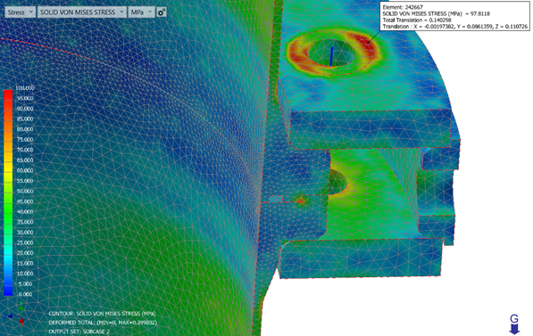
The flange design was checked using an Autodesk Nastran finite element analysis. A pre-stress linear static model was used to apply the installed bolt tension. (Bolt tension was estimated as a value that would exist after warm-up to the design temperature). Bolts were modeled as beam elements. i.e. A more complex 3D bolt model is unnecessary because the bolts are in loaded in simple tension.
ii) Input data
The input data used for the FEA calculation shown in Fig 9 is arbitrary for purpose of illustration.
The metal “C” ring seals have been modelled as imposed forces along lines corresponding to the top and bottom seal contacts.
A bending moment applied to the joint as a whole equal to the maximum allowable bending moment for straight 316L pipe using ASME B31.3 Table A allowable stresses.
Internal pressure 2 bar g.
Material properties corresponding to 650℃.
iii) Materials (Typical)
| Item | Material | Comments | |
| Pipe | 316L | 1.4404 | Austenitic stainless steel. Resistant to scaling at high temperature. |
| Pipe ends | 316L | 1.4404 | Austenitic stainless steel. Resistant to scaling at high temperature. |
| Flanges | 316 | 1.4401 | Not welded. Specified minimum carbon level to ensure creep strength. |
| Support Rings | 316L | 1.4404 | Rolled and seam welded. Creep strength is not a factor because of the low compressive stresses. |
| Bolts | ASTM A286 Gr 660 | 1.4980 | Precipitation hardening austenitic stainless steel. |
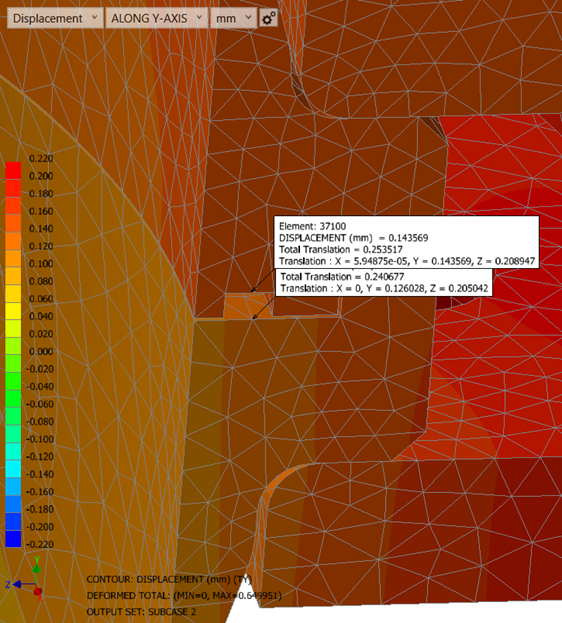
iv) Results
All through wall stresses are significantly below typical values of 1% in 10,000 hours creep strain. (See Fig 10).
Note ! Stresses below the 1% creep in 10,000 hours does not mean that the joint will not creep. Creep will continue but at a reduced rate. Further analysis would be required to estimate an operating life. The seal ring is displacement controlled. The seal ring will operate as long as structural metal-to-metal contact is maintained at the joint periphery.
Joint opening in the seal area at maximum bending and pressure is within tolerance of the metal “C” ring. Metal to metal structural contact is maintained for the joint as a whole.
(Ref ASKZN Stainless Steel Directory)