
Constant effort pipe supports
When is a constant effort pipe support not constant?
By Andrew Weighell [email protected]
- Objectives
- Introduction
- Constant effort pipe supports – all types
- Design Standard MSS-SP-58
- Free Body Diagrams
- Spring friction calculation (Numerical example)
- Conclusion
- Thoughts and discussion
- References
1. Objectives
To discuss the consequences of constant effort spring support load tolerance.
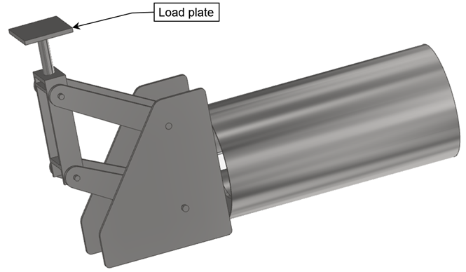
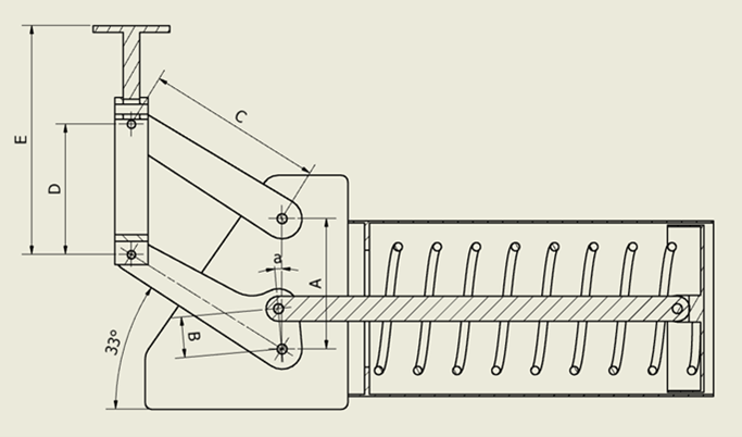
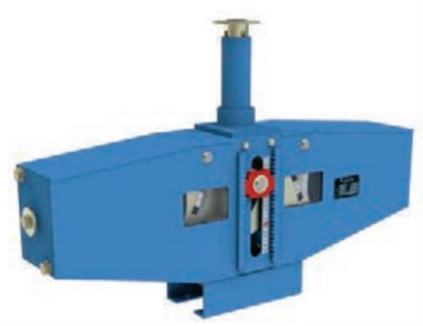
To analyse the effect of lateral load applied to the load plate of a bell-crank constant effort spring used in a base spring configuration. (See Figure 1).
Coincident lateral load imposed on a spring load plate could be created by
a) Friction or
b) Lateral force components if the applied load is not in perfect alignment. e.g. Pipe shoe sole plate not perfectly parallel with the spring load plate.
2. Introduction
2.1 All types of constant effort springs
Pipe stress calculations always assume that all types of constant effort spring support are perfectly constant. i.e. The vertical load carried by the constant effort spring is assumed to be unchanged at all positions and directions of spring travel.
However, in reality, all types of constant effort springs are never perfectly constant. The imposed load will vary depending on spring position and in the direction of travel. e.g. The load carried by the spring when moving downwards could also be different to that when moving upwards.
Manufacturers design constant effort springs to have the smallest possible load variation. However, load variations are never zero.
A constant effort spring would normally be designed to have a maximum load variation when new of 6% (MSS SP 58).
The best possible as-new variation for any type of constant effort spring is about 2%. However, a load variation of 2% would require a special order with individual load testing.
2.2 Base type constant effort springs – all types
Base type constant effort springs are used to provide support from underneath the pipe.
Base type constant effort springs are in two main groups. i.e.
i) Vertical motion with lateral motion – performance is affected by coincident lateral pipe support loads. e.g. Bell-crank type. (See Fig 1).
ii) True vertical motion – performance is NOT or minimally affected by lateral pipe support loads. e.g. Fig 4 and Fig 5.
2.3 Base type constant effort springs – with bell-crank.
The performance of base type constant effort springs using a bell-crank with unguided load plates are negatively affected by lateral loads applied on the spring axis. (Such springs have minimal or zero capacity to resist loads applied at 90 deg to the spring axis).
Base type constant effort springs using a bell crank are subject to sliding motion between the pipe and the load plate even if the pipe remains stationery. The horizontal sliding motion causes a lateral friction force. The lateral friction force directly affects the load carried by the spring linkage.
Lateral forces applied to an unguided spring load plate are caused by:
a) Friction induced by lateral motion of the load plate as the linkage follows a circular arc. i.e. The load plate travels both vertically and horizontally.
b) Friction induced by lateral motion of the pipe relative to the spring as the pipe warms and cools.
c) An out-of-parallel misalignment between pipe and load plate.
Note!
i) The parts of the discussion below that relate to bell-crank type base springs assume that the pipe remains perfectly stationary in plan. i.e. The pipe motion is perfectly vertical.
ii) Horizontal pipe movement relative to the load plate could completely change the discussion below. For example, when the pipe moves in the opposite direction to that caused by the rotation of the spring support geometry. i.e. The pipe either moves with or moves against the lateral motion of the load plate.
3. Constant effort pipe supports – all types
3.1 Constant effort load tolerance
Constant effort pipe supports do not create perfectly “constant” load resistance. All real-life constant effort springs are subject to some load tolerance over their range of travel. The maximum allowable load tolerance is defined by the design standard used.
For example, constant effort pipe supports that are manufactured in accordance with MSS SP 58 have a maximum deviation equal to 6% of the specified load. [Ref 3].
Definitions (for purpose of this discussion)
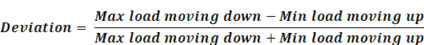
a) Deviation
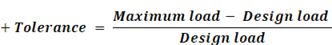
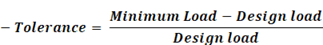
b) Tolerance
Notes
1. Deviation is independent of any specific load values. e.g. Nominal design load.
2. Deviation is ONLY equal to tolerance if the “Design load” is equal to the average of “Maximum load moving down” and “Minimum load moving up”.
The magnitude of the deviation (tolerance) and the way deviation (tolerance) changes with travel is affected by the geometry of the particular spring support assembly.
Some spring designs have deviations and tolerances as low as 2%. Very low tolerance springs are normally individually tested and certified.
It is noted that the manufacturer’s specified deviation and tolerances are based on new equipment tested under ideal conditions. Corrosion and dust particles in the operating environment could significantly compromise the performance of the constant effort spring over its operating life.
Load changes during operation are affected by the quality of the linkage pivot points. For example, pivot points using engineered bearings with weather – dust seals should cause less lifetime deterioration of spring performance than for an unlubricated pin without any low friction bearing or weather – dust seal. (See Figure 2).
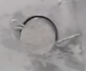
Fig 2 Pivot point without lubrication or dust seal.
3.2 Constant effort spring types
Most constant effort springs are one of three types.
a) Bell-crank without load plate guides. (See Figs 1, 3).
b) Bell-crank with top plate guides. (See Fig 4).
c) Profiled cam type. (See Fig 5).
4. Design Standard MSS-SP-58
4.1. Spring load deviation and tolerance
MSS-SP-58 Table 5 specifies deviation for “Constant Support Hangers” as follows

“Maximum Reading Moving Down and Minimum Reading Moving Up shall be within 6 % of specified load”.
Rearranging equation to calculate load tolerance from specified load.
L = Specified Load (Assume equal to mean load to give equal +/- tolerance “x”).
L + x = Max Reading Moving Down
L – x = Min Reading moving up
d = Deviation from Specified Load
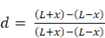
Simplifying

If d = 0.06, then x = 0.06L.
For example, if L = 20 kN, then x = 1.2 kN.
The load carried by the spring varies from 18.8 kN to 21.2 kN.
For example, if the spring was moving downwards with a load of 21.2 kN, the load carried by the spring could reduce to 18.8 kN when changing direction to move upwards. i.e. A reduction of spring load capacity of 2.4 kN. i.e. 12%
What happens for a real spring when the load resistance of a constant effort spring changes during its travel?
Any load difference that is “NOT” carried by the spring has to be carried by other pipe supports or equipment nozzle connections in the system.
4.2 Pipe weight tolerance
Pipe weight tolerances applies to any type of pipe support. However, the effect of pipe weight tolerances on constant effort springs is particularly important.
Calculated pipe support loads are affected by the tolerances on
– System dimensions
– Pipe weight
– Pipe fitting weights
– Valve weights
– Flange and flange bolt weights
– Weight pipe supports components connected to the pipe
– Weight of insulation and cladding
– Weight of contents
– Snow and ice
– etc
For example, weight tolerances for ASTM A106
| Pipe Size | Weight tolerance |
| NPS 12 (DN 300, 323.8 mm) and smaller | -3.5% / +10% |
| NPS 14 (DN 350, 355.6 mm) and larger | -5% / +10% |
Is it realistic to hard stamp a spring casing with an installed load of perhaps “17693 N”?
Even if the pipe stress software was theoretically 100% accurate and the system consisted only of pipe, the actual load could be from 16808 N to 19462 N!
Why not specify “17.7 kN”? It would save time finding punches for the person stamping the name plate? Even “18 kN” would be accurate enough.
Do you check weigh pipe prior to spring installation?
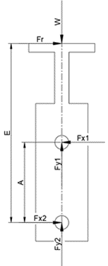
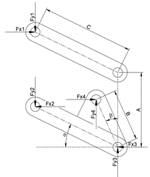
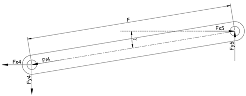
5. Free Body Diagrams for bell-crank base springs
6. Spring friction calculation for bell-crank base springs (Numerical example)
6.1 Introduction
The purpose of this section is to use a numerical example to discuss the effect of friction on a bell-crank type constant effort spring supports.
Note! The loads and dimensions used for the example are intended to be in the same range as manufactured springs but are otherwise arbitrary. The load and dimensions used in the example are not based on any particular spring manufacturer.
Any comments and discussion apply equally to all pipe supports of the same design rather than to any manufacturer.
6.2 Methodology
The effect of friction on base type constant effort springs has been calculated by
a) Traditional manual calculations using free body diagrams.
b) Dynamic simulation using Autodesk Inventor.
The results are identical for both methods.
Results for Autodesk Inventor Dynamic Simulation are included below.
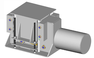
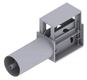
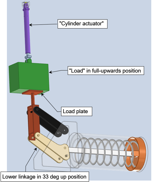
The dynamic simulation using Autodesk Inventor used a CAD model of a “virtual” test rig. (See Fig 9 below). The load plate of a base type constant effort spring is driven up and down by a “virtual” hydraulic actuator. The “load” is constrained to move vertically.
(The separate “load” and “hydraulic actuator” is for visual explanation and is otherwise unnecessary).
6.3 Input data
Starting load = 20032 N (Arbitrary value)
Two calculations are included. The imposed movement applied to the spring load plate has been input as a series of linear ramps. Two cycles of movement are included to show load change from upwards travel at end of the first cycle to downwards travel at the start of the second cycle.
Calculation 1 33 deg up → -12 deg down
Imposed movement = 400 mm down → 400 mm up → 400 mm down → 400 mm up
Calculation 2 33 deg up → 0 deg down (Linkage horizontal)
Imposed movement = 290 mm down → 290 mm up → 290 mm down → 290 mm up
Calculation 2 has been included to study the effect of the load friction NOT reversing part way through each movement stroke.
Note: The starting load and movement are arbitrary values used for the purpose of creating a representative calculation for illustration and discussion.
“Full upwards” = Linkage 33 deg above horizontal.
“Full downwards” = Linkage 12 deg below horizontal.
Load cases considered.
1) Load plate and linkage bearings frictionless.
2) Load plate friction = 0.1, bearings frictionless.
3) Load plate friction = 0.1, bearing friction 0.1
Bearing diameters for purpose of friction calculation
i) Spring tie bar to lower link = 40 mm
ii) Lower link to support casing = 40 mm.
iii) All other top and bottom link bearings = 20 mm dia.
iv) All other bearing frictionless.
4) Load plate frictionless, bearing friction 0.1 as for Case 3 above.
6.4 Results
6.4.1 Calc 1 Displacement Range +33 deg → -12 deg (400 mm vertical movement)
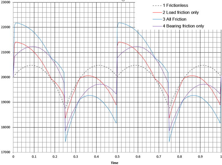
Table 1 Spring Imposed Movement (See Fig 10)
| Time | Imposed Movement |
| 0 → 0.25 | Downwards 400 mm (Starting from 33 deg up. See Figure 9). |
| 0.25 → 0.5 | Upwards 400 mm |
| 0.5 → 0.75 | Downwards 400 mm |
| 0.75 → 1 | Upwards 400 mm |
Table 2 Deviation and Load Tolerance
| Load Case | Deviation | Tolerance (+) | Tolerance (-) | ||
| 1 Frictionless | 4.1% | 450 N | 2.2% | -1153 N | -5.8% |
| 2 Load friction only | 7.2% | 1377 N | 6.9% | -1507 N | -7.5% |
| 3 All Friction | 11.4% | 2147 N | 10.7% | -2403 N | -12.0% |
| 4 Bearing friction only | 8.3% | 1202 N | 6.0% | -2058 N | -10.3% |
| Notes1. Tolerances relative to starting load | |||||
Table 3 Load Case 2 Load friction only (See Fig 10)
(Friction between load and load plate, all bearing frictionless).
| Time | Motion | Load change | Comments | |
| 0 → 0.25 | Downwards 400 mm | Start | +1.4 (7%) | Load increases from ~20 kN to 21.4 kN to initiate down movement. |
| Max | +1.4 (7%) | Load reduces continuously from first peak | ||
| End | -2.2 (-11%) | Load reduces to 19.2 kN at the end of the down movement | ||
| 0.25 → 0.5 | Upwards 400 mm | Start | -0.8 (-4%) | Load reduces from 19.2 kN to 18.4 kN to initiate up movement. |
| Max | +1.0 (5%) | Load increases to 20 kN at mid-deflection and then reduces. | ||
| End | -1.0 (+5%) | Load reduces to 19 kN at the end of the up movement. | ||
| 0.5 → 0.75 | Downwards 400 mm | Start | +2.4 (+12%) | Load increases from ~19 kN to 21.4 kN to initiate down movement. |
| Max | +2.4 (+12%) | Load reduces continuously from first peak | ||
| End | -1.4 (-7%) | Load reduces to 19.2 kN at the end of the down movement. | ||
| 0.75 → 1 | Upwards 400 mm | Start | -0.8 (-4%) | Load reduces from 19.2 kN to 18.4 kN to initiate up movement. |
| Max | +1.0 (5%) | Load increases to 20 kN at mid-deflection and then reduces. | ||
| End | +0.8 (+4%) | Load reduces to 19 kN at the end of the up movement. | ||
6.4.2 Calculation 2 Displacement Range +33 deg → 0 deg (290 mm vertical movement)
i.e. Friction on load plate does not reverse part way through the full up or down stroke.
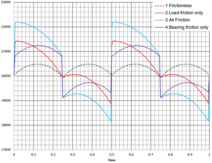
Table 4 Spring Imposed Movement (See Fig 11)
| Time | Imposed Movement |
| 0 → 0.25 | Downwards 290 mm (Starting from 33 deg up. See Fig 9). |
| 0.25 → 0.5 | Upwards 290 mm |
| 0.5 → 0.75 | Downwards 290 mm |
| 0.75 → 1 | Upwards 290 mm |
Table 5 Deviation and Load Tolerance relative to starting load
| Load Case | Deviation | Tolerance | Tolerance | ||
| 1 Frictionless | 1.2% | 439 N | 2.2% | -60 N | -0.3% |
| 2 Load friction only | 6.3% | 1380 N | 6.9% | -1161 N | -5.8% |
| 3 All Friction | 10.0% | 2154 N | 10.7% | -1888 N | -9.4% |
| 4 Bearing friction only | 5.1% | 1193 N | 5.9% | -887 N | -4.4% |
7. Conclusion
No type of constant effort spring support is theoretically constant – even though all pipe stress software assumes it is.
Unguided bell crank type constant effort base support are significantly affected by lateral loads caused by friction and load misalignment.
8. Thoughts and discussion
8.1 What happens when a constant effort spring is not supporting the actual load?
How big is the “missing load”?
What direction is the “missing load” acting?
Where does the “missing load” go?
The only thing that can be said with certainty is that the “missing load” has got to go somewhere.
The only place the “missing load” can go is to another fixed support or fixed point in the piping system. When every adjacent support is a spring support, the nearest fixed point is the often a nozzle on the vessel or mechanical equipment.
Several years ago, I was involved with an investigation into a power boiler which failed. Luckily, nobody was injured. (Even better, my finger prints were not on it!). The failure did not cause a leak of high pressure and high temperature steam. However, many tubes were very seriously bent! The first 7 pipe supports from the boiler were spring supports. The first 4 spring supports were constant effort. The combined load tolerances on the constant effort supports would have been bigger than than the allowable nozzle nozzle loads.
(A related and equally serious problem with any constant effort spring is the risk of settling over time – particularly if the pipe expands downwards. Friction as shown in Fig 10 above means that the support has to be unloaded before it can move upwards. If full upward return movement cannot take place, then the pipe does not return to its starting point. The next temperature cycle would then start from a lower point. Over time, the pipe would ratchet downwards until the restoring forces were overcome or something broke).
8.2 What can be done to prevent problems caused by load variations in ANY type of constant effort spring?
Do you actually need to use a constant effort spring?
Would you be better off just using a long travel variable spring?
The biggest benefit of using a variable spring is predictability. Spring extends – load increases! Spring shortens – load decreases!
Alex Matveev made a very interesting point when we discussed constant effort supports. Constant effort springs are not used in Russia! Russian standards refer to using multiple spring cans in series to create long travel supports with very low stiffness. Russian design standards listed by Alex include OST 108.764.01-80, OST 24.125.109-01 (ОСТ 108.764.01-80, ОСТ 24.125.109-01).
Is it better to keep a design simple and workable? Or should you aim for perfection but risk creating real world problems? If you were building tanks, would you use inline road wheels or over-lapping road wheels? Overlapping road wheels would give a better load distribution – but would seize-up with frozen mud and take ages to repair?
8.3 What can you do about bell crank type constant effort base springs without all round guides?
Should you even be using this type of spring? It is physically impossible to avoid the consequences of relative lateral movement discussed above?
As with any type of constant effort spring, would you be better off in reality using a long travel variable spring?
In my experience, both constant and variable base springs carry a risk if the pipe slides over the support. My first choice would always be a hanging rather than a base spring support. A hanging support is always more predictable? Could you design a pipe support structure to carry a hanging support? Maybe a trapeze beam hung from posts at each side of the pipe?
Hanging pipe supports of any type always want to swing back to their starting points thus avoiding questions about stress range discussed here.
Variable and constant effort base spring load plates that do move vertically must be guided if subject to lateral forces for which they are not designed. For example, lateral forces could cause binding with of a simple “bottle jack” type variable spring can.
Additionally, the pipe should be guided if there is any risk that the pipe might slide (“ratchet”) off the spring support – it does happen!
Base spring load plates that follow a circular arcs cannot be guided all round. The only option for constant effort base springs subject to lateral loads are those designed to resist lateral loads. e.g. Figs 4.1, 4.2 and 5.
9. References
| Title | Comments |
| 1. Constant Effort Spring Supports Carpenter and Paterson Asia | “…maximum deviation +/- 5% of the specified load.” |
| 2. Piping Technology & Products Inc | “The MSS standard provides for a tolerance of 6% in the constant load through the travel range”. |
| 3. ANSI/MSS SP-58-2018: Pipe Hangers and Supports – Materials, Design, Manufacture, Selection, Application, and Installation | Table 5 states “Maximum Reading Moving Down and Minimum Reading Moving Up shall be within 6 % of specified load” |